

Architectural terra cotta is a defining characteristic of 19th and 20th century architectural styles. The fired clay masonry provided architects with a new way to express artistic creativity. Today, the terra cotta industry faces numerous challenges related to facade restoration projects. One of the most prevalent is the use of alternative materials as a replacement for architectural terra cotta. Alternative materials have become an increasingly desirable solution for replacement of distressed terra cotta units over the last fifteen years, primarily because of their perceived lower costs and shorter fabrication lead times. Yet, at the same time, the use of terra cotta in rainscreen cladding systems has begun to gain traction in the world of contemporary architectural design.
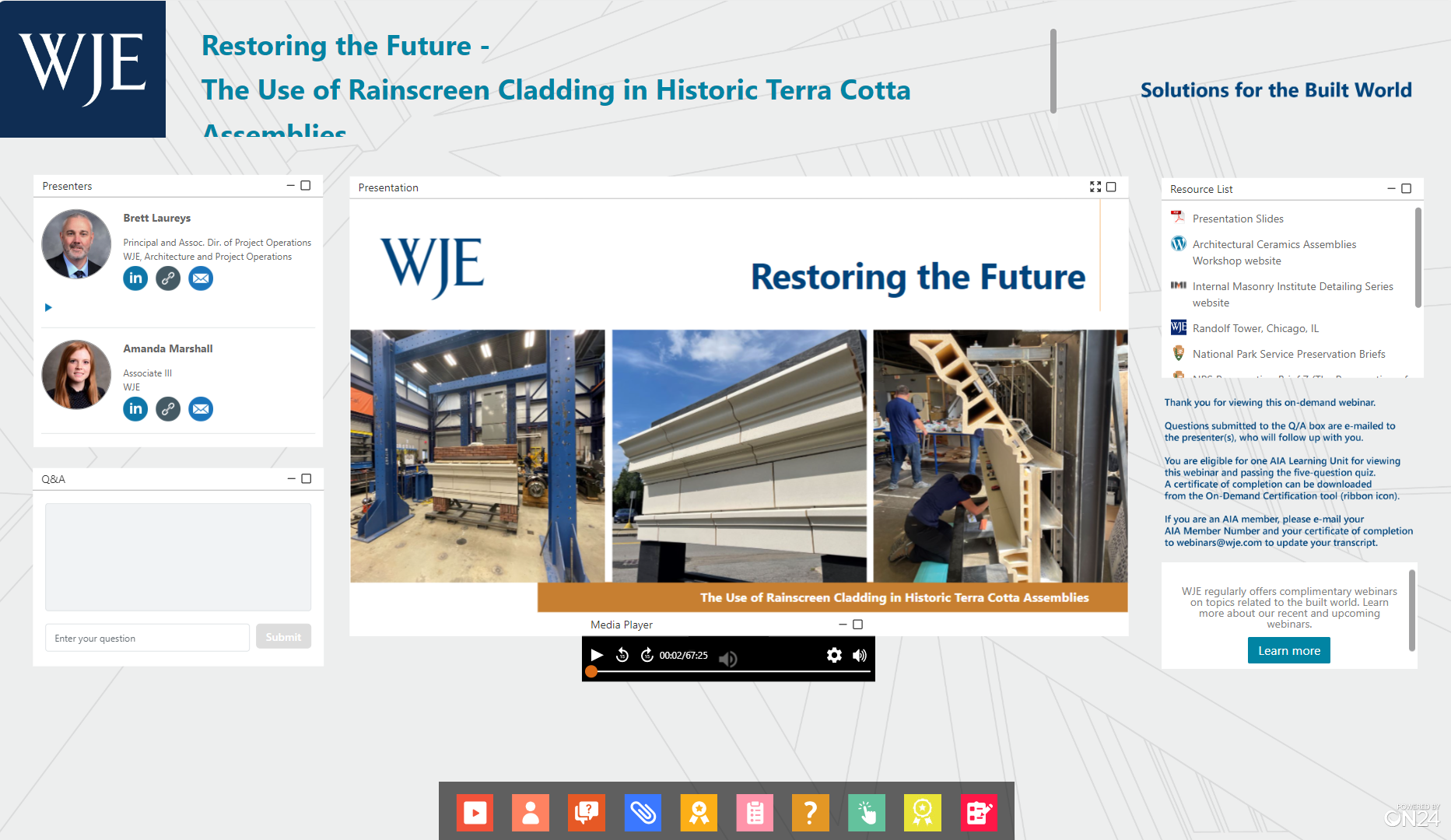
In this webinar, engineer Brett Laureys and architect Amanda Marshall discuss the results of a WJE in-house project aimed at designing a more contemporary terra cotta rainscreen cladding system to replicate a historic cornice assembly at a lower cost and with a faster fabrication time than traditional architectural terra cotta. The system was originally created as part of the 2022 Architectural Ceramics Assemblies Workshop and then tested in WJE’s Janney Technical Center.
more to learn
View this webinar in our interactive audience console to earn 1 AIA learning unit, access related resources, submit questions to the presenters, and download a certificate of completion.
LIZ PIMPER
Hello, everyone, and welcome to today's WJE webinar, Restoring the Future: Rainscreen Cladding in Historic Terracotta Assemblies. My name is Liz Pimper, and I'll be your moderator. During the next hour, Engineer Brett Laureys and Architect Amanda Marshall will discuss the results of a WJE in-house research project aimed at designing a more contemporary terracotta rainscreen cladding system to replicate a historic cornice assembly at a lower cost and with a faster fabrication time than traditional architectural terracotta. This presentation is copyrighted by Wiss, Janney, Elstner Associates, and now, I will turn it over to Brett to get us started. Brett?
BRETT LAUREYS
Thank you, Liz. Well, welcome, everyone. We're really excited to share our story on some research that our team just recently completed. Today, we're going to talk about using a contemporary terracotta rainscreen system to replicate a historic terracotta cornice assembly. Amanda Marshall and I are going to walk you through our design, the mock-up assembly, and our structural testing experience. So, we wanted to start off by saying, why do we feel this research was necessary? Many of our clients and industry partners have been asking for a more cost-effective solution for replacing terracotta cladding assemblies.
In lieu of using alternate materials for this, our team wanted to explore options for creating a lighter weight, more cost-effective system while maintaining terracotta as the historic replacement material. This is an AIA presentation, and so we have our four learning objectives. We'll go through the key differences between historic and contemporary terracotta fabrication. We're going to explain the recent challenges with reconstructing these historic terracotta assemblies and we'll touch on alternate systems. We're going to talk about our mock-up and the test procedures that we went through for that. Then in the end, we'll give you a little quick summary at the end and the benefits of the system that we've put together.
So, our roadmap as we go through this morning, we're going to start with evolution of terracotta cladding. We'll talk about those challenges of reconstructing the assemblies. We'll touch on some alternate replacement materials. We'll do a little research, talk about our research and design for this new system. We did several mock-ups for the system. We'll touch on that and then get into our structural testings and findings. So, to start, we want to start off on the basics. We'll start with the evolution of terracotta cladding systems and production just to set the table for today. Historic terracotta assemblies were often constructed using a massive masonry around a steel building structure.
Many of the decorative projecting elements were supported with a combination of steel gravity supports along with laterals. So, in this case here, we have some steel cantilevered outriggers that pick-up support of those cantilevered terracotta elements and also hang the brackets that are below. The other steel elements are the lateral ties that tie back those terracotta units into the massive masonry behind. Corrosion of these steel elements is often the main cause for cracking and spalling of the terracotta elements and repairs then are required. Overall, terracotta all by itself is a very durable clay material. It's lasted for over 100 years in many buildings and it's the corrosion of these steel elements that cause hazardous conditions.
So, for this example, we have some terracotta bracket assemblies that are hung from those steel elements. Over time, those often go in disrepair and there's significant corrosion. In the photograph, you see that that bracket assembly has actually spalled and fallen from the building. So, many of these cornice assemblies were honestly removed from buildings and we'll touch on that in our presentation because they created safety concerns and there's high cost to put them back. So, they did not. So, first, we're going to start off with how these pieces are made, and so hand-pressed terracotta is the traditional means of fabrication. This method is still used today in restoration.
So, this process includes, first, you create a model from an original sample, and that model is usually 10% larger because of the shrinkage of clay during firing process. From that model, we create a plaster mold and then you assemble that into a five-sided box. Within that box, the laborers now hand-press that raw clay into the mold. So, as you can see, this takes a lot of labor. It's not cheap to do and it takes time. So, each one of these individual pieces now has to be pressed into this plaster mold. Over time in a short time, the plaster mold dehydrates the clay, allowing the form to hold, and then the mold is removed and then those pieces are dried and finished. Hand-pressed terracotta units, what makes those up? We have some internal webs, and in general, these pieces are open.
So, they're meant to be a little more lightweight than solid stone and include those internal webs for structure and end in sidewalls. Generally, the traditional terracotta hand-pressed pieces had end walls and internal webs that were one and a half inches thick. Overall, terracotta really gained its popularity in the early 1900s over stone, and that was due to speed of fabrication and cost at that time. The more modern means of producing terracotta units is extrusion. The extrusion process requires a development of detailed shop drawings, and you can see here here's an example of one of the shop drawings for a steel die that is now cut to create these extruded pieces.
So, like pushing Play-Doh through a plastic shape as a kid, we now take the wet clay and we push that through the die. So, it is extruded out on a table and then those pieces then are wire cut to length. As you can imagine, the hand-pressed terracotta units take much more labor and time to make. We can make a couple of those a day. In this instance, you could make hundreds of pieces fairly quickly by running them through the extruder and wire cutting them. I'll touch on this a little later on terracotta rainscreen, but terracotta rainscreen panels are made using this extrusion process. So, they use an automated extrusion process today, but overall, we just wanted to make the point that extrusion by far is the most cost-effective means for creating terracotta and cladding buildings, but it is limited on the shapes and the profiles that can be made.
As part of WJE's ongoing efforts to help the historic masonry restoration industry, we've collaborated with the International Masonry Institute in developing details for reassembling historic terracotta assemblies. These are used by the craft workers and those others in the industry that are in terracotta restoration. These were developed to provide guidance for structural support, anchorage, and waterproofing of these rebuilt assemblies. As you can see here, this is an example that was put together for extruded terracotta. So, different than hand-pressed, the anchorage becomes much different. So, we put together these details to give guidance on how to anchor extruded material since that's the way the industry is leaning.
As part of our work with IMI and the two of the terracotta manufacturers in the United States, we assisted with designing these mock-ups. These mock-ups, again, they're at IMI's facility. We have the hand-pressed units on the right and the extruded units on the left. We wanted to show the difference in the anchorage of these units from a lateral perspective, and then in order to be more cost-effective, terracotta manufacturers definitely are looking for ways to extrude as many of these pieces as possible on restoration projects. The structure of the units are much different. They're a little bit lighter in weight and they're anchored differently.
So, that's why we wanted to show this for the craft workers so they could mock this up and work through it in real time. Last, we wanted to introduce the components of a modern terracotta rainscreen system. Terracotta rainscreen systems have become more popular in new construction over the past 10 years. Mostly I would say due to their appearance, their durability, and their fire rating. The typical system includes an open joint system with thin-walled terracotta panels, which were those extruded panels I just showed you, and they're over a backup assembly. So, let's start here just to give a little bit of a generic rainscreen system. We have the backup wall assembly here in orange, which in one case here is a CMU backup.
The other case is metal studs over gypsum sheathing. Both of these cases have some air or moisture barrier to handle any water that gets into the system. Then we have the blue, which is the anchorage to the backup. For CMU walls, we have these either aluminum or galvanized clip angles. In most cases, we have horizontal galvanized or steel girts that make up the system that support horizontally across the backup wall. Next, most of these are proprietary per the rainscreen manufacturer, but this is a vertical aluminum track. So, you'll hear a lot of times and we'll refer to it today as aluminum track end clip. That is proprietary to each system and supports the terracotta panels as they're assembled. Last, we have the terracotta rainscreen panels themselves.
So, extruded clay, that somewhat is set in the track end clip system most of the time with gaskets and then there's clips for lateral anchorage. Those clips are here shown in red, and I'll blow that up a little bit. So, here's a typical example of one system that is out there. These clips, they clip into the aluminum track system, and then there's gaskets along the vertical. The key to these systems is that they're anchored and the gaskets allow for movement and they limit water penetration. They are open joint, but they try to limit as much water penetration as possible.
Many of these systems are meant to be able to be removed and replaced. So, an individual panel, if it gets damaged, there are ways to remove those panels and replace them. Okay, now I'd like to turn it over to Amanda and she's going to discuss some of the challenges we see with reconstructing these historic assemblies.
AMANDA MARSHALL
Awesome. Thank you so much, Brett. So, reconstructing historic terracotta assemblies presents its own unique set of challenges. These historic assemblies are a massive masonry and many of the terracotta units are very heavy, weighing anywhere from 100 pounds to over 1,000 pounds each for some of those larger units. To rebuild in kind requires a significant amount of labor to lift the heavy units and set them integral with the backup masonry. Often, chain falls and hoists are used to aid masons in lifting and setting these behemoth units. Another challenge in doing so comes with transporting the units up onto the building.
On some projects, we're able to use a mast climber, which has a much higher weight capacity and it allows masons to load that platform with all of the material and tools that they'll need for the day. However, if a project uses a swing stage or a lift, the weight capacity is much lower and creates a need for lots of up and down movement to pick up material. So, that's not only bringing up the new terracotta, but also transporting back down all of that material that we're removing, terracotta, brick, and other stuff too. So, that's just a labor-intensive, timely process. So, aside from the cost and time associated with that labor comes the cost of the material itself. In the left photo, we see a variety of different decorative terracotta units.
Those units are each hand-pressed since those decorative elements cannot be extruded through a die with the current technology that we have. So, with each individual unit, of course, comes the time and the material to create it, which in turn can contribute to some of the strain of cost and lead time for materials on a project. So, while our preference as historic preservationists is to rebuild with traditional materials, project constraints can often leave us facing the reality of needing to consider alternatives. So, what happens when those project constraints leave owners and professionals with limited options? These two photos really demonstrate a classic case of a cornice having been removed and replaced with essentially a face brick parapet wall.
Really, if you look up as you walk around in a city like Chicago, you'll probably begin to notice buildings of all sizes and uses with something similar. In many cases, the decision to remove a historic assembly was most likely made due to the cost implications of replacing distressed terracotta and buildings like the one shown in these photos make excellent examples of potential for reconstructing using alternative methods. This is the Olympia building in Miami. The entire ninth floor water table is cracked nearly from end to end due to severe corrosion of the underlying steel supports. Based on our initial assessment, we determined that the entire band would require replacement. This is a really great example of a continuous terracotta building element that is costly to repair in kind.
It requires more than just removing the cracked units and putting back new ones. Enough terracotta and backup materials need to be removed in order to fully access that underlying corroded steel, you also need to repair that steel and start to think about if you want to put in any flashing or any other type of repairs before putting back your masonry backup and your terracotta. So, the cost or time requirements of that entire process may put a strain on the option to use traditional methods. So, how do we restore these damaged elements in a cost and time effective way? One option that professionals can help owners to save time and money is by using alternate materials. So, let's dive into that for a second. Why do we use alternate materials?
One of the most prevalent challenges in today's terracotta restoration industry is the time that it takes to fabricate new terracotta. In this list, we can start to see that there are several nine critical steps for replacing terracotta units. These span all the way from removing the existing damaged unit all the way to shipping the units back to the job site to be installed. This process often takes over a year from start to finish, which can significantly impact the project schedule and the overall costs. So, we're always asked, where can we save time and money? One of the ways that we can save time and money is by using alternate materials. This is often a very realistic option for a lot of the projects that we're working on.
Lead time and cost are two of the driving factors for the exploration of using those materials in lieu of an original material. Preservation Brief 16 is a very helpful resource for understanding when and how substitute materials would be acceptable or appropriate for use. That brief cites standard six of the standards for rehabilitation, which states that new materials must match the old in composition, design, color, texture, and other visual properties. The brief also notes that flexibility is an option when necessary. So, what exactly are alternate materials and how are we seeing them on terracotta rehabilitation projects? One of the most common ones that we've been seeing in projects that we're working on is glass fiber reinforced concrete or GFRC. That comes in two formats.
It comes in a unitized format where essentially the concrete is poured into a mold that's taken from the original terracotta unit. So, that essentially aesthetically looks very similar to the terracotta unit, and then it receives a coating to mimic the glaze. We also see GFRC in a panelized format where the concrete is sprayed into a mold to create a thin panel. The other that we see quite a bit is FRP, which is a thin shell. It's a non-load-bearing material that is made up of gel coat, polyester resin, and glass fibers. So, think fiber glass panel when we're talking about FRP. So, both panelized GFRC and FRP are, of course, lighter than a single terracotta unit, and that makes them a desirable option from an installation standpoint.
The caveat, however, is that the panelized materials cannot support gravity loads, and they're really not as resistant to impact as traditional terracotta or even unitized GFRC units. So, what do these alternate materials look like in the context of a rehabilitation project? The Marquette Building in Chicago was one of the examples where panelized GFRC was used to rebuild a historic cornice assembly. As you can see in the left and the middle images, at one point, the cornice had been completely removed, and in 2001, the building's owners began a multi-year process of replacing the cornice with panelized GFRC. So, in these photos, we can see how the panelized GFRC was installed with steel and Unistrut backup support.
The GFRC panels are typically several feet in length and they include faux joints to mimic the look of terracotta. As you can imagine, this system is significantly lighter than the original terracotta system. Another example of using an alternate material was with Randolph Tower. This building underwent a fairly comprehensive terracotta rehabilitation project several years ago, and the decision was made to use panelized FRP at the 43rd floor parapet. That was done so that the owner could save on time and on cost. So, you can see in these two photos how that FRP really blends in with the terracotta around it. So, here's just a couple of close-up images.
As you can see, multiple terracotta units were replicated using a single panel of FRP, and again, you can see those faux joints creating what would be a spandrel panel. So, these panels were three-eighths of an inch thick with returns on both sides, and each panel weighed about 100 pounds in comparison to what would've been about 2,000 pounds of terracotta and backup masonry. So, you really have to think about some considerations when putting in a panelized system like this. At [inaudible 00:19:59], we did include a masonry backup and we had to provide structural support for wind loading with such a thin panel in lieu of something that had more mass to it.
So, even though we have these very reliable alternate materials that we can use when necessary, our preference from a historic preservation standpoint will always be to use terracotta as a replacement material. One of the primary reasons why we prefer to use terracotta would be its durability. These fired clay materials have really withstood the test of time. A lot of the buildings that we're working on that have terracotta have been standing for well over 100 years, and a lot of the time when the terracotta is not interfaced with corroding steel, it's still in very good condition. It also has very good impact resistance, and it has the fire ratings that play a huge role in why we use masonry on buildings.
Then in terms of the substitute materials, we don't have that full life cycle of a building to be able to compare how GFRC and terracotta or FRP and terracotta will compare over a century of time on a building. We know from just the way that these materials are manufactured, GFRC receives a coating whereas the terracotta's glaze as part of the firing process. So, of course, the coating will require some maintenance. So, from that standpoint, we would absolutely prefer to use terracotta if we know that it has that test of time. Finally, we really do want to align our choices with preservation guidelines, and for us, that means advocating for the use of historic materials in lieu of alternate materials at any opportunity that we can. So, how does this all come together?
We've taken you through how terracotta is manufactured and what the challenges are and what options we have had in our industry for addressing those challenges, but how can we take it a step further? How do we meet the needs of our clients, whether those be financial or schedule-driven, while also maintaining the historic preservation standards and guidelines? We know that the terracotta industry continues to adapt as architectural design styles change over time. So, how can we utilize those adaptations on our historic masonry projects? Really quick, Brett walked us through the evolution of how terracotta is manufactured. Let's revisit those adaptations for a moment to think about how we can utilize that technology in our projects.
Over time, production methods for terracotta have changed and adapted as technology advances. Where units were originally hand pressed and slip cast, which we see in that top row of photos, many non-ornamentally units are now extruded or ram-pressed using hydraulic presses and then they're cut to length. This saves time and cost and production. Additionally, over the past 10 years, extruded terracotta rainscreen systems have gained popularity and contemporary architecture due to their unlimited color and design options, their unique appearance, their speed of installation, and also their fire ratings. So, our team got to thinking, how do we use this modern rainscreen technology to help us replace historic terracotta? We start with research, of course. So, I'll turn it over to Brett to talk about our team's approach.
BRETT LAUREYS
Thanks, Amanda. So, as Amanda said, our clients are asking us on just about every terracotta restoration project, "Again, how do we save time and money and meet the historic guidelines?" So our group at WJE got together and we wanted to develop some ideas to try to attempt to solve these issues. So, we thought of introducing a modern rainscreen technology into a historic restoration. So, where did we start? Well, our team initially reached out to a group that developed the Architectural Ceramics Assemblies Workshop, or we also call that as ACAW.
In 2016, Boston Valley Terracotta, along with Carnegie Mellon University School of Architecture and the University of Buffalo School of Architecture and Planning, that group developed a yearly event and it brings together professionals from the architectural industry and academia. It offers the participants to explore terracotta, right? They want to have innovative building solutions, and they want to allow people to further understand how architectural terracotta can be used in large scale assemblies. So, since 2017, I personally have been involved with ACAW. I participated on a couple of teams in the past few years, and I was more of a support role. We helped with testing. We helped with the structural anchorage of these pieces.
Well, in 2022, our team convinced ACAW to allow us to be part of the workshop and really explore options for developing a more economical system for terracotta replacement and restoration. Now, this group is mainly focused on new construction and focused on innovative new ideas. This is now a new innovative idea in restoration. So, we're also seeing that the timeframe for terracotta production has gone up. As Amanda said, our clients want to expedite schedules. We're seeing more and more of these projects become negotiated. They're leaning more towards that design-build project delivery. So, this requires collaboration. It's collaboration with the design team, the contractor, and the manufacturer.
So, when we put this project together, why not do the same? So we put a research and design team together that included a masonry restoration contractor, which was Central Building Preservation, and then the manufacturer was Boston Valley Terracotta. We worked through this whole design process together as a team. In early 2022, when this whole process started, we began brainstorming. We met several times and we wanted to come up with what would we use for replicating a historic building element and how do we save time and cost? We started by coming to the conclusion that we thought we should use the IMI terracotta mock-up. So, we had been involved with IMI.
We had hand-pressed and extruded units, which you saw in the photo in the assembly earlier. How can we put the next level to that? How do we put them next to each other and show the differences? So we wanted to maintain the historic profile but reduce the weight. Just so that we're all on the same page, we wanted to point out a couple of things from nomenclature standpoint that we'll talk about as we move ahead. We have the upper course here, which is the cornice or water table. We'll refer to the flat ashlar as the flat piece of terracotta that's there in the middle of the spandrel, and then we have a profile window head unit. So, just as we move ahead and give a better understanding.
After several of these sessions, we outlined the design where we maintained the exterior profile of the original terracotta. So, in the green here, we wanted to maintain that profile, so that it looked exactly the same, but introduced thin walled units and integrate that more into some systems that are more of a standard track end clip system that's in the rainscreens. This design had to allow for a lot of flexibility. As you know in historic restoration, these buildings aren't plumb level. They've moved over time. So, we had to allow as much of movement within the backup structure as we could. One of the biggest things was trying to reduce the weight, and that started with introducing a rainscreen on the lower part of our design.
So, it went from 250 pounds of material to 75, and then our extruded cornice, which was a 300-pound piece of solid terracotta that now is 80 pounds. So, you can imagine if you want to lift a 300-pound piece, that's going to require some hoists or lifts versus 80 pounds can be lifted by two craft workers. Overall, our goal was to reduce the weight of this assembly by 70%. In elevation, we wanted to maintain the joint layout and profile of the terracotta units to match historic. Also, for our mock-up and our design, we wanted to introduce this window head assembly. Often these cornices have that and have a return soffit, so we wanted to integrate that in. We developed four unit types to be extruded as these thin wall units.
The terracotta that we extruded was five-eighths inched thick material versus that one and a half. So, again, we're using less clay material and lightening that up. So, I'll go through this again. So, we have three units across the cornice and water table here in orange. We have three units across the flat ashlars in blue. We have four units across the window head profile, and then there are two soffit units underneath. Again, we designed this as part of the assemblies workshop. So, at ACAW, they ask you to put together a mock-up of your assembly, and this is what our design ended up being. In section, you could see there are significantly less clay material and the backup structure is really a combination of stainless steel and aluminum components.
So, I'll go through each of these a little bit just to give you a flavor of what we put into our design and talk about some nomenclature. So, we started with how do we anchor this whole assembly back? It started with using some off-the-shelf. We can find these at a local hardware store even of a stainless steel Unistrut. So, those vertical Unistruts provide lateral and gravity support. Now these will be anchored to the backup assembly. Now that's going to vary between concrete steel and brick. So, we had a steel assembly that we anchored our mockup to, but this would be the part that varies, but for the most part, we're using these vertical Unistruts because they allow for vertical movement across the system. Next, we'll talk about the cantilevered Unistrut supports.
So, up at the top, we used some standard components from Unistrut where there's a bracket assembly and also a cantilevered portion here in the upper part with the small orange arrow. Then we transfer down. These units are hung. So, they're hung in the orange arrow there from a three-eighths inch diameter stainless steel threaded rod that is attached to a quarter inch bent plate. Then that is anchored into the red, which is a Unistrut that's along the backside of the cornice units, and those are anchored to the actual terracotta piece with the yellow, which is a stainless steel drilled and tapped plate. So, the intent of all of this was that we would allow for movement up and down to adjust for joints and also in and out of plane of that photograph.
So, we could move this in all directions to account for the variability that we see on historic buildings. The next part is our more contemporary track end clip rainscreen system. We modified this slightly because we had to put additional components in to meet the joint pattern of the historic assembly, but really this is their standard aluminum track end clip from Boston Valley. Then we put in these horizontal aluminum girts that provides support to the actual backup structure. Then last, we have some one-inch thick soffit units that were created to finish off the top of the window head opening.
Those here in red, those are anchored with undercut anchors into the backside of the piece and then hung to the steel structure above. As you can see, this assembly was really designed for a complete replacement of a cornice, and it's really not likely to be cost-effective if you have one piece here or one piece there. It's meant to be a replacement for a continuous assembly. So, now I'm going to turn it over to Amanda to talk about the next step in 3D modeling for our project.
AMANDA MARSHALL
Cool. Thanks, Brett. So, Brett just gave us a sneak preview of what some of these components of the system looks like as we were building them in person. But really throughout that design process, we were pretty much working in 2D, sketching over details and drawing things in AutoCAD. So, bringing the design from 2D to 3D was a critical part of transforming this concept into a reality. So, we worked with Boston Valley to model and tweak our design in the 3D modeling software called Rhino. Having that model that showed not only the units but also the backup support illustrated in three dimensions allowed us to gather dimensions and view the model from all angles. That was really an integral part of our mock-up and construction phases.
We really had this 3D model open on a laptop anytime that we were building our mock-ups, so that we could spin around the model and take quick measurements and just figure out how things work together. So, let's move into the build environment now. The first thing that we did in preparation for our big ACAW build was meet with the team at WJE's Janney Technical Center in July of 2022 to build our mock-up. This mock-up was really a critical part for us to be able to practice the installation of the backup components, particularly the spacing of the Unistrut, placement of support brackets, and the installation of our anchors.
We took note of lengths and spacing for each component and we photographed each phase thoroughly, so that we could replicate our process efficiently once we were at the University of Buffalo for our build. The mock-up also gave us the opportunity to resolve problems as they occurred and make adaptations for our next build, including simplification of our installation procedure, modifications to anchor components, and we also compiled a list of tools and materials that we would need to order just to make our job easier once we were there. So, I'm going to hand it back to Brett to dive into our ACAW build.
BRETT LAUREYS
All right. Thanks, Amanda. So, in August of 2022, our team arrived at the University of Buffalo. You could see our backup frame here was already constructed for us. This is the maker space or laboratory at the University of Buffalo. So, all of the teams meet here and go through the assembly process during a week-long event in August each year. So, our team, along with seven other teams, spent about two and a half days fabricating and assembling the mock-up. Each of the seven teams had a different mock-up assembly of what they're choosing. WJE and Central had a team of seven of us, and I'll say I think we were the first team that had coordinated T-shirts for the event since they started this in 2016.
During the assembly, we really focused on pre-assembly of the backup structure and then application as many of these support elements on the terracotta units as we could prior to installation. We wanted to try to make this as modular as we could. You could see here with the orange arrows, we pre-assembled all of the Unistrut and hanger assemblies on the back of the water table units before they were put into place. Then the upper right photo with the orange arrow, that then just slid very nicely into the Unistrut brackets and were anchored with one bolt. We were not then allowed to adjust the vertical height and horizontal distance based on all of the adjustments we had in the Unistrut assembly.
I'll say that one of the things we also learned on this is that architects and engineers do make for some pretty expensive labor. So, here's some of the images of the final mock-up from ACAW. We did some, I'll say, fake brick and painted MDF to simulate the appearance of masonry wall and potential of flashing above the cornice. This was showcased at the evening event with all of the other projects that were out there. In the end, we were super happy with the result of this, the appearance matching the historic cornice profiles with more of a modern system. So, if you looked at it from the front, I don't know that you would tell that this thing is a rainscreen type system.
At the end of the week, all of ACAW teams presented their work and findings at an in-person event, and it was broadcast virtually. We do have a resources list that includes the website with some of the recordings and some of the notes. So, we got done and our team was super excited about this mock-up, but what do we do now? Our team wanted more. We wanted to make sure that this was going to be able to perform in the field. So, in 2022, WJE as a company, we introduced internally our Ask the Structure Research Program to our staff, and this program allows WJE to make a substantial investment in our in-house research each year, so that our staff can develop further on our expertise in solving problems for our clients.
So, in 2022, our team was awarded one of the first in-house research projects as part of that program, and that really entailed creating a second mock-up assembly. Of course, we're a company of testing, so we wanted to test it. Now I'll turn it over to Amanda who's going to talk about our next build.
AMANDA MARSHALL
Awesome. Yeah, so as Brett mentioned just now, after our first build, we were looking for what to do next. The problem wasn't solved yet, and we still had some more work to do. We were so excited that we had this new opportunity to pursue in-house research and testing to be able to take it where we wanted to go. So, in December 2022, our team presented our initial findings and mock-up experience to our internal network at WJE, particularly to our folks with expertise in historic masonry and historic preservation. So, that was a really awesome opportunity to hear what their feedback were and some suggestions that they have. Based on all of that, we got together again in January 2023 to create what we call our ACAW Build 2.0.
So, really this was pretty much the same design as what we had done previously, but this time based on a couple of suggestions and a lot of conversation internally, we made the decision to seal the joints in our rainscreen system. So, that was primarily the main change that we made. So, after we completed Build 2.0, it was actually transported to the Chicago area IMI Training Center, where it was showcased at various events over a significant portion of 2023. So, we were very happy that we were able to strap this thing to the back of a truck and it safely made it to IMI and back to WJE in one piece. So, here's a quick side by side of our assembly in comparison with similar terracotta cornice assemblies at IMI where they can be used to compare the evolution of terracotta.
So, bringing this all back together again, I know we already talked about it, but in the image on the right, we can really see the transformation from hand-pressed unit to a slightly more contemporary extruded unit. Then all the way to the left, we can see our more contemporary rainscreen system. So, while the profiles are very similar, the weight of these is significantly reduced. We were thinking it's probably somewhere in the neighborhood of 70% in weight reduction. So, as with any change in design, there are many considerations to be made before applying this system in a real-world application. Ultimately, the idea is to provide an alternative option to traditional terracotta that still uses the original material.
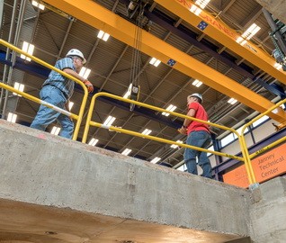
So, what's next? We had built this assembly in full twice, and we needed to start thinking about how this would work in the context of a real building. So, for us, the most logical next step would be testing. We started by thinking about what loads this assembly would be subject to in a real world application. On January 31st, 2024, we set up the terracotta mock-up assembly between two large sewer reaction frames, which we can see are the large blue frames in the photos. This was housed in our Janney Technical Center Structural Laboratory.
This steel mock-up frame was braced in order to simulate a stiff solid masonry backup condition, and we really started with four tests on the mock-up in order to better understand how this lightweight terracotta system would behave in the field, particularly during maintenance work. So, the tests included a rope line fall safety test. So, imagine in a fall event, a lifeline will be pulled down. So, we want to see how do these units behave when subject to this tension created by a lifeline. We also wanted to explore both the downward and the upward loads on the edge of that projecting cornice, which could potentially happen from a swing stage getting caught on either of those edges going up or down.
Then finally, we did a soft body impact test, and so that would allow us, again, using a swing stage, there's going to be some movement. There might be a scenario where the swing stage actually impacts these units. So, we want to see how do those perform when subject to those loads. So, I will turn it back over to Brett to go into a little bit more detail on each of those tests.
BRETT LAUREYS
Thanks, Amanda. So, this initial test was to simulate a personal fall event. So, we had a three-quarter inch diameter rope over the face of the cornice assembly, and we did this at the midpoint of the center unit. The rope was protected at the top of the wall, but we left it unprotected at the edge of the cornice, which is actually unfortunately is a common thing. From our past research and testing during fall events, we assumed a 300-pound person that had some tools and that person in a fall event would probably put a tension force on the rope between 1,750 and 2,500 pounds. So, of course, we tested it to 2,500 pounds. The load was applied using a chain hoist and load cell, which you see in the left photograph.
Deflections for each of the cornice units were recorded independently, and we recorded up to a half inch deflection in the center. Basically, the rope had enough friction along that front edge. It put a horizontal inward force on the cornice, and then actually, it was slipping as we loaded it, but it was putting a downward force on the front edge of that cornice as well. We had about a quarter inch deflection in the piece to the right of the center, but that was mostly due to the adhesion of the sealant that was within the joint, dragging that piece along. But after the testing, both cornice units returned to their original position and we had very limited permanent deformation of that piece.
Second, we tried the downward load. This test was performed to simulate, say, a suspended scaffolding, catching it as it was moving down. We used a hydraulic ram and nine-inch long steel channel to simulate a roller that would catch it. That load was determined using assuming 2,000-pound rated scaffolding motors. We had a 2000-pound swing stage with equipment. We added a safety factor of one and a half and divided it by the two motors. So, we ended up using a 1500-pound downward load in the center of the right cornice unit. Deflection was recorded in that unit and the center unit as we did this, and we had up to 1.74 inches of deflection in the center of the right unit and then we had about a 0.4 inch deflection in the center.
Now, that deflection is not typical for a historic masonry assembly. Normally, these assemblies are packed full of mortar and brick and are very stiff. This assembly we found had a lot of flexibility to it. So, the thing is when we have terracotta cornices that are mass masonry and we hit them with a scaffold, there's a chance that that front edge of the cornice actually fractures off and breaks. In this case, we had no damage to the terracotta unit. We had some significant deflection. There was some damage to the Unistrut outriggers and steel plates as you could see in the two yellow arrows. We had some permanent deformation in the plates in the threaded rods, and then the outriggers actually had some play or slop in the bolt hole, so they deflected downward as well.
So, there's a lot of flexibility in this system, but it returned and there was no damage to terracotta and it was still structurally anchored back to the building. The third test was to simulate a swing stage, catching it on the front edge while moving upward. So, it's a similar thing that a historic cornice normally might break the edge off because it's so stiff. We applied a similar load using the hydraulic ram upward. We determined the load by assuming 2,000-pound rated motors with three times for the load for the stall load of the motor. We assumed the weight of the scaffolding and personnel. So, ultimately, we wanted to test this to 2,500 pounds as an upward force on the cornice. I'll say that as we got into testing, we were only able to apply about 1,600 pounds of upward force.
We had an inch and a half deflection, and we got to a point where we had some fractures in some of the terracotta pieces at the anchorage. We couldn't apply the load anymore because it didn't have structural capacity for upward movement. So, here as that unit was pushed upward, it actually rotated the bottom edge of the cornice assembly, putting pressure on the backside of the ashlar course, which was in the track end clip. It broke the back of the panel at the track end clip. Now, this was a pretty aggressive test and pushing up on here. What it was is we had so much movement in the system that it applied that load on the ashlar. If we did it again, we could probably provide a larger joint, so that it wouldn't put pressure on that ashlar panel.
We also did get cracking of some of the anchorage at track end clip because of the movement of those panels. They can only handle limited movement, and so we did get some of that. Any spalls that we had were held in with the sealant that was within the joints. As with all the other tested, this actually rebounded pretty well, and it was within a half inch of tolerance from original. The last test performed was done to evaluate impact loads on the assembly. We focused on impacts at both the window head and the cornice as you can see in the yellow two arrows. This testing was in accordance with some European standards, one of which has since been withdrawn.
Basically, we selected these tests because we reviewed several terracotta rainscreen specifications in the industry, and the industry is leaning much more towards a lot of these impact tests, concerned about durability and capture if something does happen in an event. For this test, basically, it's a burlap bag of 100 pounds of steel shot. It's then elevated to a height of 10, 28, and 40 inches of drop height. So, you could see here, here's the drop height. We used the crane, and then we had a release mechanism that released the soft body bag. It was hit on the surface of the cladding from each of those heights. It introduced 88, 258, and 370 foot pounds of energy to the surface of the cladding.
At the window head assembly, we didn't have any damage at 10 inches, but once we hit 28 and 40 inch drops, we observed some movement in the lower C course or that profile window head assembly. It actually pushed up into the ashlar units causing some cracking at the anchorage, and then those balls again were held in place. Now, the panels were still anchored back to the assembly, but we did get some fracture at some of the support conditions. Realize this is a pretty aggressive test as well for hitting these units. At the upper cornice, we found that we had up to one inch deflection when it was impacted from 28 and 40 inches. The system was, again, very flexible and the steel framing backup allowed it to deflect.
We did get some tearing of the sealant, and we did get some permanent deformation of some of the steel conditions in the back. If this was a solid masonry assembly, it probably would've broken that piece and you would've had a fractured piece that could have been falling to the ground. So, what are our overall takeaways? We had some fairly large deflections, much more than a traditional mortar set system, but it rebounded well and we had no damage to any of the terracotta units during testing. We did have some permanent deformation of some of the hanger rods and quarter inch bent plates. Again, we had about at least a half inch of permanent deformation along the front edge of the cornice.
I'll say that we also had some of these areas where we had impact damage that the track end clip system could not handle the amount of movement that it saw, but those were at the higher levels of force. Then last, we saw some upward movement in the cornice assembly. To be completely transparent, this assembly was designed for gravity support and lateral design. We did not design it for upward load. So, we will need to adjust the system to take care of that. All right. I'm going to turn it back to Amanda to wrap us up and talk about our final findings.
AMANDA MARSHALL
Great. Thank you, Brett. Yeah, we came away from all of this research and testing with a lot of takeaways, a lot of things to think about for the future, and just thinking about what are some of the challenges that we'll face as we bring this further. So, a lot of those future considerations will be project specific. We have a few highlights of improvements or things we change based on our mock-ups, one of those being in staying consistent with the aesthetic of historic assemblies and to capture any potential fragments from impact damage. For right now, our stance would be that we would treat the joints with sealant and provide a secondary drainage system behind the cladding.
So, this is a photo of what the joints look like when they're open versus this photo shows what the joints look like with sealant. So, we felt that this aligns a little bit better aesthetically with a historic assembly. There are several other project specific considerations to be made. These would include details for how we treat corner conditions, offset conditions, or end conditions. Also, how are we approaching the more decorative units, the ones that would be traditionally hand-pressed? We would need to think about how we could integrate that into the rainscreen system. We also would need to approach each project a little bit differently based on what the backup structure is.
A lot of times we're running into common brick or clay tile, concrete. In this photo, we can see a mix of all three of those. So, while it's great to have a very continuous consistent backup for our testing, in real life, there are going to be differences and that's something that will need to design specific to each building. There are also a lot of opportunities for simplification, particularly with the anchorage details and thinking about we can reduce the overall amount of stainless steel elements that we're putting into the backup. Really, the more that we can reduce the time and the material will be better. There are also other challenges, particularly with acceptance from the masonry trades.
Restoration masons are not used to working with this type of prefabricated stainless steel backup assembly. We can predict that the cost will be a little bit high until they become more comfortable with installing these systems and also getting this into training at IMI will be really beneficial for the future of this. Really for the future, we're looking for opportunities to bring this option to our clients. We hope that this is eventually a more cost-effective solution for replication of terracotta cladding elements while using this long-standing and durable masonry material. So, in summary, this exercise of designing and building and testing the rainscreen terracotta cornice allowed us to carefully study how this system would look in a real world context.
We really feel that this was a success, and we're so excited with the information that we gathered from our research and our testing. With the system where the terracotta units are 70% lighter than a traditional terracotta unit, the cost and the lead time benefits really do go hand in hand. We do believe that opportunities for this system exists in historic preservation industry and the benefits of historic tax credits for adaptive reuse projects really make this a viable option for restoring or reconstructing historic assemblies.
So, we're just so excited to be able to share what we've learned and how we really got here with the industry. We'd really love to know what your feedback and your questions are, and we'd also really like to know how you maybe envision this system in today's build environment. So, with that, I'll turn it over to Liz, so that we can get started with some questions.
LIZ PIMPER
All right. Thanks, Amanda, and thanks, Brett. That was a great presentation. Lots of good information. All right. Let's take our first question. How soon will this realistically be commercially available to implement? Is it available now or in months, years?
BRETT LAUREYS
I'll take that one. So, to be honest, this is available now. We have the technology and there's the components that can be easily made. I'll say that we would have to adapt it for the actual as-built conditions on a specific project, but overall, the system as designed and as tested, we feel like we could implement that on a project. Actually, we have a couple projects right now where we're looking to put this in as an alternate to see how it factors in with a cost, how it's going to be received by the masonry restoration industry.
LIZ PIMPER
Okay. Next question, are the rainscreen systems approved applications for installation in seismic prone areas? Do warranties cover damages from a seismic event, not catastrophic or minor shaking and rumbling, et cetera?
BRETT LAUREYS
I guess I'd say first to start off, we did not test this from a seismic perspective. We talked about it, and we still may do that. The hard part with it is that the flexibility with the frame that we constructed our mock-up on, and we hadn't intended it to be that way. However, I'll say that this system is extremely flexible, much more flexible than a historic mass of masonry. We believe it would perform very well in a limited seismic event. Again, we're not necessarily producing the system for anything. It's basically to help our clients. So, we would want to look at that some more further. It also made it on a truck ride back and forth, a half hour each way. So, we feel it would probably perform pretty well, but we have not tested it in a seismic application at this point.
LIZ PIMPER
Okay. The next question, since the cause of failure of existing historic terracotta assemblies tends to be the corrosion of steel, what is the anticipated lifespan of these repaired/new terracotta systems that use steel clips and reinforcements? Is stainless steel used in lieu of galvanized, or is it generally considered cost prohibitive, or do the new assemblies stay dry enough that the steel's lifespan is indefinite?
BRETT LAUREYS
Amanda, you want to take that one?
AMANDA MARSHALL
Sure. Yeah. So, to address the question of what type of steel we're using, we are using stainless steel Unistrat. We also have aluminum components with the backup design for the rainscreen system. So, from that standpoint, those materials do have a bit longer of a service life than traditional steel. However, there probably would be a need for some maintenance, of course, down the line, over the life cycle of a building. In terms of the terracotta, that should have a very similar lifespan to what a traditional terracotta unit would have, just from the standpoint of it being constructed from the same materials, using the same processes of extruded terracotta that we've seen in historic applications that we already do see it. Brett, is there anything else you want to add?
BRETT LAUREYS
No, I think that's good.
AMANDA MARSHALL
Okay.
LIZ PIMPER
All right. The next question, what is the average or approximate lead time for the extruded terracotta units? Traditional terracotta was over one year. What does it reduce to with the extruded design?
BRETT LAUREYS
That's a trick question. I would say, I don't know if I can answer that. It's going to depend on how busy the manufacturers are. The only thing I can say is that based on all of our discussions with the manufacturers, that the lead time would be significantly reduced in that we're creating a couple of dies. These pieces can be made much quicker. So, I don't know that we can say a set date, but the manufacturers are telling us that by producing these in an extrusion manner, that we would get a fairly significant reduction in time. Now, the time also includes creation of the die, the shop drawing of the die, and all those things. So, I don't know that I can say a specific timeframe.
LIZ PIMPER
Okay. Next question, typically, rainscreen joints are open. Why did you decide to seal the joints?
BRETT LAUREYS
Amanda?
AMANDA MARSHALL
Yeah. Part of the reason that we initially decided to seal the joints was really quite aesthetic. We showed a photo of how the entire assembly looked without the joints. For us, the aesthetic of having those dark lines in between the terracotta units didn't fit right with our aesthetic expectations for the historic assembly as a whole. We also learned from our testing that some of the impact tests that we did actually caused some spalling and loosening of small portions of the terracotta adjacent to clips, and those actually were held in place by the sealant. So, that reaffirmed us in making that choice.
There was a lot of conversation either way about what the implications would be of sealing them versus of leaving them open. For us, it just felt right to seal them, but that's still very much something that we were thinking about and also we would need to think about what secondary drainage would look like behind the rainscreen.
LIZ PIMPER
All right. We've got time for maybe two more questions. This one says, "Were there any tests that looked at performance against thermal movement and stresses? Any considerations for cyclical loading due to seasonal effects?"
BRETT LAUREYS
We did not specifically do any testing regarding thermal movements and stresses. However, I'll just say that that was one of the reasons that we wanted to anchor all of these pieces independently and leave the joints either open or with sealant. So, in historic masonry assemblies, we worry about introducing new brick and new terracotta because over a longer span, we will get an increase in moisture expansion.
We'll also have thermal stresses and thermal movements that will build up. In this system, the thermal movements and stresses are all accommodated with each individual unit and there's joints. So, to be completely honest, I don't know that we really are concerned about that just because we don't have a continuous assembly that's all lined up and would build up those stresses a longer length. They're actually accommodated in each individual unit.
LIZ PIMPER
All right. One more question, why did you choose not to include creating the top portion of the cornice? It seems like creating the top portion using other materials is not historically accurate, hard to make watertight, and it is cumbersome to connect other materials to the terracotta.
BRETT LAUREYS
Based on weight, of course, we would prefer to put back a historic assembly. That's the first, but because we're seeing so many alternate materials that have similar configurations to this, we wanted to introduce the historic terracotta. So, one of the things that we did talk about was putting some terracotta blocks on top of the cornice, but ultimately, we made the decision that it wouldn't be 100% historically correct, but it would allow us to have access from the top side to put all the anchorage in and then cover things up with sheet metal on the projecting elements. We just felt like trying to introduce the terracotta up on top of the horizontal surface would become more difficult.
Is it an ideal application to not have full terracotta back as the water table assembly? Probably not, but we had to make some concessions in certain areas. We also know that if we have masonry above there, we have to come up with some structural support or structural gravity support for the masonry above. So, there's some things with this and it has some limitations, but ultimately, that's why we wanted to create it, to put it back as a continuous assembly across the face of a building, not just individual pieces.
LIZ PIMPER
Great. Thanks, Brett, and thanks, Amanda. As I said, unfortunately, that is all the time that we have for questions today. Thanks for joining us for the presentation and thank you so much for hanging on to the end. We hope it was educational and worth your time. So, again, thank you so much for your time and we hope you have a great rest of the day.
RELATED INFORMATION
-
 Brett E. Laureys, Principal and Director of Business DevelopmentWJE Northbrook MORE >People | Brett E. Laureys, Principal and Director of Business Development
 -
 Our professionals balance the need to provide practical, long-term solutions with the ability to... MORE >Services | Historic Preservation
 -
 We offer in-house expertise for a full range of investigation, analysis, and design services... MORE >Services | Architectural Finishes and Materials