


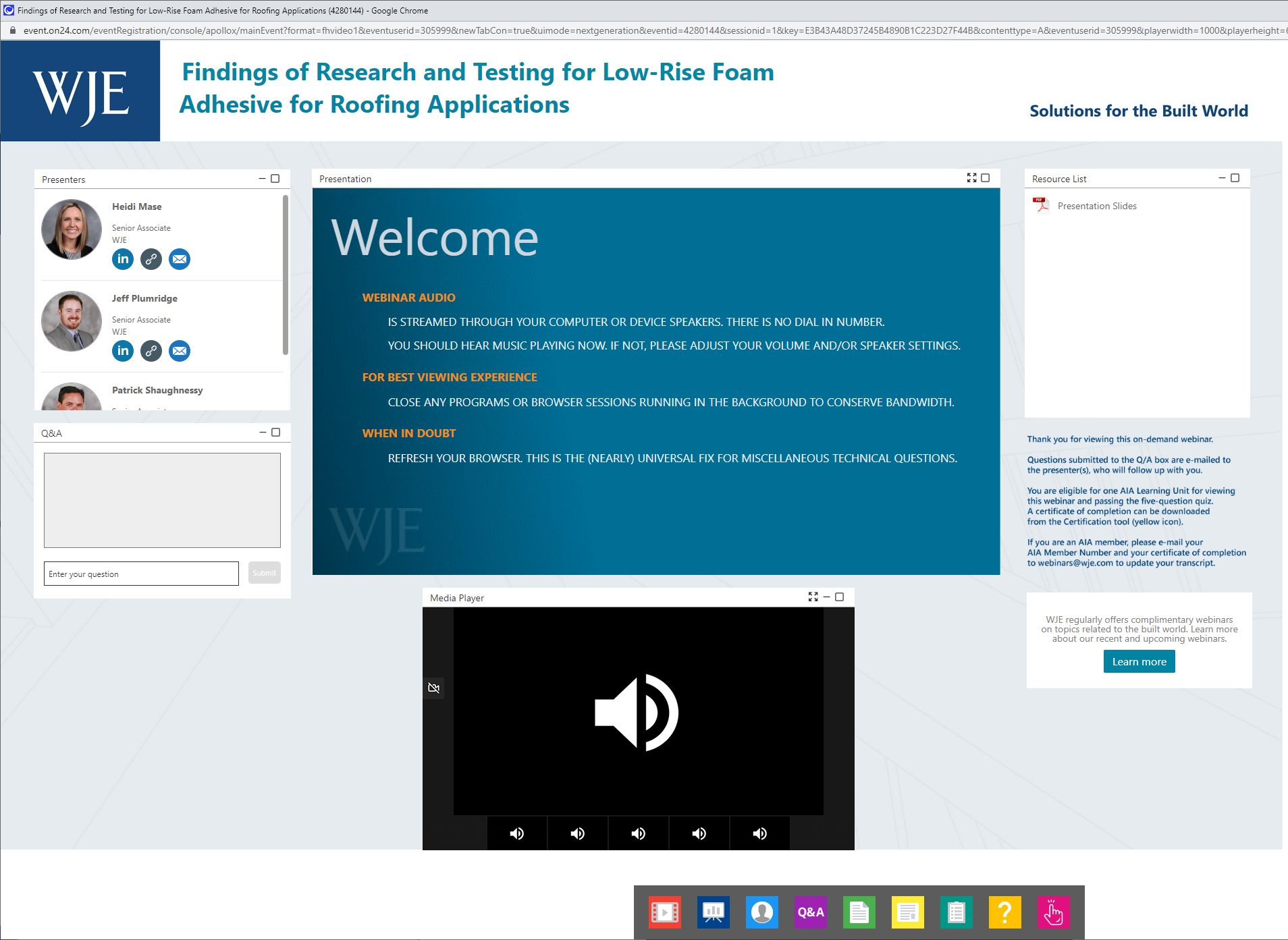
Low-rise foam adhesive has been used to bond layers of polyisocyanurate roofing insulation for many years, yet little testing and research had been conducted to determine the optimal spacing and strength of cartridge-dispensed adhesive ribbons, particularly on full-size insulation panels. In 2019, the Midwest Roofing Contractors Association (MRCA) engaged WJE to investigate the effect of variable ribbon spacing on the adhesive’s bond capacity with polyisocyanurate insulation using three different ribbon spacings on two facer types and measuring the direct tensile loads at failure. Our findings were shared in 2019 and 2020 and can be viewed in this webinar.
MRCA subsequently engaged WJE to build on the low-rise foam adhesive research and testing by studying the effects of shelf life and application temperature on the tensile strength of the adhesive, physically and chemically testing products made by two manufacturers.
In this webinar, WJE architect Heidi Mase, chemist Jeff Plumridge, and roofing expert Patrick Shaughnessy provide an overview of our 2020-2021 research and testing program and will summarize findings and conclusions.
By the end of the webinar, you will be able to:
- Summarize findings from WJE's research and testing on tensile strength of low-rise foam adhesive
- Describe findings of physical testing used to measure low-rise foam adhesive strength as affected by application temperature and shelf life
- Explain findings of chemical testing used to examine, measure, and identify changes in low-rise foam adhesive as affected by application temperature and shelf life
- Apply research to the design, specification, and construction of adhered roof assemblies
more to learn
View this webinar in our interactive audience console to earn 1 AIA HSW learning unit, access related resources, submit questions to the presenters, and download a certificate of completion.
Jeffrey Plumridge, Senior Associate
Patrick Shaughnessy, Senior Associate
LIZ PIMPER
Hello everyone and welcome. My name is Liz Pimper and I'll be your moderator for today's WJE webinar, Findings of low-rise Foam Adhesive Testing Program. During the next hour, WJE writing experts, Pat Shaughnessy and Richard Koziol will provide an overview of the research and testing program. Summarize the results including insulation factors found to have a greater impact on overall bond capacity and assess the impact of this research on the design specification and construction of both. This presentation is copyrighted by Wiss, Janney, Elstner Associates, and now I'll turn it over to Pat to get started, Pat.
PAT SHAUGHNESSY
Thanks Liz. I want to thank everybody for joining us today. We did some pretty interesting testing and I think all of you will find it interesting as well. By the end of the presentation you should be able to summarize the testing methodology, and results that were used for the low-rise foam insulation to teach some testing. Explain the differences between the various ribbon spaces for the different types of insulation facers that are common in the industry. Identify the failure mechanisms of the facers in regard to wind uplift strengths and describe insulation techniques that can help achieve optimal performance and rifting systems that are adhered using the low-rise foam adhesives. Goals of today's presentation are to one, provide an overview of the Midwest Roofing Contractor Associations research project. I will be referring to the Midwest Roofing Contractors Association as the MRCA for the duration of the presentation.
Then also we will summarize the results of the testing that was conducted on the insulation, that was adhered with the low-rise foam insulation adhesives. Then finally at the end of the presentation, we will take questions. Before we get too far, I want to make sure that everyone has a basic understanding of the components that are typically included in a roof system. I know that there are a lot of you out there that this may be some basic knowledge, but I also know to some people out there that may not have as much knowledge about roofing systems as everybody else. Starting from the bottom up, we have our roof deck pictured here is a metal roof deck.
Other common types of roof decks that you'll run into are going to be concrete wood, would be a little more prevalent out West in the Northwest? Then there's some specialized roof decks such as gypsum or tectum panels typically run into those and retrofit roofing construction. Then over that we have our first layer. In this slide we're showing a thermal barrier or a substrate board which is commonly used with a metal roof deck and that's mechanically attached to the roof deck and you'll see the low-rise foam adhesive which is basically the crux of what we're talking about today, applied in what we call ribbons or lines of adhesive that are at predetermined spacings so that's installed on top of this substrate board and then over that goes our first layer of insulation. We'll be referring to the insulation polyisocyanurate or polyiso insulation that was used for the testing. If the rigid insulation board that has what's called a facer on the top and bottom, and besides the foam core is visible.
Then over that we put more adhesive ribbons and then common in today's roofing construction there's going to be multiple layers of roofing insulation so we set that material in the adhesive and try to achieve it where we have the joints from the top layer and the bottom layer offset from each other to reduce air movement within the roofing system. Then over that commonly, we'll see what's called a cover board, which is a high density material that helps give the roofing system impact resistant to protect things are inadvertently dropped on the system, or even offer some protection during hale. Then finally over that we install our roofing membrane.
In this picture we could have a PVC, a TPO, or even an EPDM single-ply roofing system. There are other systems out there such as the bur-ply built up asphalt or multiply built up asphalt, commonly referred to as like a tar and gravel roof or a modified bitumen roof membrane so it can be roofing 101 with the components are, we will be really concentrating in this presentation on those two layers of polyester annual rate, along with those ribbons of adhesive.
Little background on how we got to where we are, the MRCA issued a request for proposal in May of 2019 and it was prompted because of issues that some of their member contractors were having with consultants regarding rates of application of heaps of being performed by a human so there's a little bit of variation in the spacing, and sometimes it's a little less than perfect. That was kind of what was the impetus behind everything. In the MRCA request for a proposal was a problem statement and it was really that heart of the research that was completed and that read what impact does variation in foam ribbon spacing have on ultimate roof uplift capacity?
Also with the RFP, MRCA had some initial thoughts on what they thought would be the basis for the testing. They wanted to have in the low-rise homes full-scale testing of full size samples. Full sized boards being 4-foot by 4-foot boards that were 2 inch thick. There are 4-foot by 8-foot boards out there, but those are commonly only used in a mechanically attached type of situation and in many scenarios and hearing those boards is not permitted by most roofing manufacturers. Then we would be using the 2-part foam urethane adhesive applied in ribbon to various spacings. Currently, the industry standards are 4-inch, 6-inch and 12-inch spacings. What is the value of the testing program for the MRCA? There's little information on how slight spacing irregularities and variances affect the ultimate bond of the insulation layers, and a little information about how the issue of spacing and how that correlates with a... and how it affects wind uplift properties of insulation.
We met with the MRCA technical and research committee taking their information and then figuring out how to best address the problem statement that they came up with in their RFP. What we came up with was that we would focus strictly on insulation-to-insulation adhesion. We, weren't going to look at the adhesion of insulation to roof decks, to vapor retarders and we're going to look at roof membrane adhesion to insulation strictly insulation-to-insulation. We would use the 4 ft by 4 ft specimens and then we would use ribbon spacings that were at 6, 12 and 18 inches. 18 inches isn't a normal spacing, but you'll see later in the presentation why we chose to go with the 6, 12 and 18 inch spacings. In order to test the full 4 ft by 4 ft specimens it would require that a custom loading apparatus be developed that could accept the full size specimens. There's testing out there that was done on 2 ft by 2 ft samples, but a 4 ft by 4 ft it's not a common material size to use for testing.
Then to go along with the full size samples, we use some companion specimens and those consisted of some smaller 1 ft by 1 ft insulation samples and then we also tested adhesive only without having any influence from the insulation boards, insulation facers so it was strictly adhesive to adhesive. Finally, at the end of the testing, we would prepare a comprehensive report that would deliver our findings. Following the research methodology, the polyisocynurate insulation was used. We used the two type of facers that are common in the industry. You have your glass fiber reinforced cellulosic felt facers, or sometimes people refer to those as paper facers and then we had our polymer-coated glass fiber mat facers. Again, 2 inch thick boards very common thickness that's used in the industry, and then the 4 by 4 ft dimension on the boards. Then the adhesive that would be used was a two-component low-rise polyurethane foam adhesive... all the materials that were used in the presentation were sourced by a single manufacturer so their guidelines for application were followed when we were putting the sampling together for the testing.
Test specimens would basically consist of two layers of insulation that were adhered with the low-rise foam insulation. Those would be bonded to plywood backers, and then the samples would then be attached to a large loading frame using peanuts and metal threaded studs. Getting into the test specimen fabrication here. You see here the 4 ft by 4 ft plywood backers that were used for the fabrication of the samples. We would adhere the insulation to those samples and then on the samples we had preset spacings that were used, and those facings were laid out in a symmetrical layout. Look here, cool video here.
Okay. Here's a video of the samples being assembled. We're putting the adhesive onto the plywood and then setting the boards into that adhesive. The adhesive was put on it at rate that would basically give us full coverage of adhesive for the boards to be set into and then over that weighted backers were placed to embed the insulation boards into that adhesive. After the initial foam rise, then we would place the boards together. Here's a slide of that. A video of that. We had an experienced MRCA installer applying the ribbons and they were trying their best to achieve the 3 quarter inch to 1 inch ribbons that are commonly required for insulation of the boards.
It will show the video again. Here we are at 6 inch spacings second slide. Second video here is of the 12 inch spacings that we use. After the... we have one more with the piece of being applied here. The boards were placed on top of each other and then weighted down with weighted backers and these backers each weighed 26 pounds. 26 pounds was chosen because manufacturer recommendations were to use a backer of adhesive that would be used to adhere the roofing membrane to the insulation and taking the weight of those backers into accounting and subtracting the weight of the plywood, we came up with 26 pounds for each one of those backers.
In this slide here, we have a completed test specimen. You here, you see the ribbon of adhesive got a nice spread on it, and that's due to placing the backers on top of the samples that allowed the material for lack of a better term, switch itself and get a wide adhesion there. Then up in the upper right-hand corner, we have our three-eighths inch metal studs that were screwed into the tee nuts that were installed prior to installation of the insulation board onto the plywood. Some of the key tests considerations that were made were standard before. What we performed here was that 2 by 2 ft samples were used and MRCA desired to have 4 ft by 4 ft samples.
We knew that in order to perform the testing on the 4 ft by 4 ft samples, we would have to come up with a custom stiffened load apparatus that could apply the load as required and in order to get proper test results, we needed to apply direct tensile force. The adherence specimens that loading onto the specimens needed to be uniform. It couldn't be any eccentricities. We couldn't peel from one end or PRI. We wanted a completely uniform load over the entire board.
Here you see we have our test frame pulling the load and from the top, from the bottom in equal amounts, and that was achieved with a customs different aluminum load frame. Here's a plan view of the conceptional test apparatus at the load frame. It was a half inch thick aluminum plate that was used and then with plenty of stiffening that was welded onto under the frame in the upper right there. That's a section view through the apparatus which shows the centrally placed loading yoke that would be used to connect the frame to what was going to be applying the force to the samples. Then finally down in the lower right-hand corner, we have how the frame was connected again with the plywood backers that had the tee nuts installed, and then the three-eighths inch threaded rod. Here's a picture of the final apparatus. You'll see the loading yoke there and the center that allows for unimpeded movement in all directions, a half inch load frame, and then the tee nuts with the threaded studs, we use a winged guts the fats and those.
You'll notice in this picture, we have some galvanized washers that were used. This photo here was a picture that was taken on a test run and we found that the galvanized washers couldn't stand up for the load that was being put onto the sample. You'll see at other pictures that we actually switched those out for something a little more substantial. The samples were then attached to this reaction frame and the reaction frame at the top had the hydraulic ram and that's how the pressure was... or the load was put onto the samples in the frame. That was mounted up on top of the reaction beam and then there's our sandwich down below with the upper load frame, lower load frame with the test specimen attached to both sides of that. Then there's a tie down legs and then all that assemblies all fashioned in through our reaction floor in our lab.
Here's a picture of the actual system that was used. This was actually left over from a previous project and it had a rating of a 2 billion pounds so we felt that this would be adequate for the testing that we were going to be using on the insulation samples. But until you see up top that is hydraulic ram, and then that connects to the samples through a cable that was brought down through that reaction being there, and the two sides of the frame and with the test specimen and then you see the tie-down legs. The sample, the tie-down legs are completely independent of the whole frame there, and all this is attached through this reaction floor that's in our lab which is 18 inch thick, concrete, heavily reinforced. You see the threaded rod there that going through the frame there, and then it's attached on the underside in the basement.
Here's a video of the samples being placed onto the frame there. You'll see they're lining up those threaded rods with the holes in the bottom and then the upper portion is lowered down over where those threaded rod are, and then attachment of the samples to the upper and lower frame was achieved with wing nuts. We just hand-tightened those so it's not the create any deflection in the plate or in the frame. After the specimens were attached into the frame, then we had some instrumentation that was attached to the specimens and we used displacement transducers. We have one that was placed at the middle of each of the 4 sides and then there were 2 additional that were placed in the upper frame near the loading yoke. The four that were placed on the sides would let us know if we were maybe getting some peeling or if any irregularity like that. Then the ones near the yoke would let us know if we were getting any deflections in the testing frame.
There was no standard the test the full sides boards in the manner that we did. We looked to a couple of other procedures out there that were established as inspiration for what we performed and so we looked at the ANSI/SPRI 1A-1 as well as ANSI FM 4474 as a basis for what... it's a starting point for how we want it to perform this testing. Big differences. These two standards use 2 ft by 2 ft specimens, whereas we were using the full size 4 ft by 4 ft insulation boards. With our reaction frame loaded independent from the sampling, we had no reaction forces that would have any effect on the testing of the sample, whereas with the two methods from ANSI/SPRI and ANSI FM, there could be a little bit of influence from the apparatus being placed on the deck that surrounds the sample area on what the final load would be.
Following those two standards, we did start the procedure as a tested it in increments so we would start at 30 pounds per square ft plus tare weight and then we held that for one minute and then the load would be incremented from there at 15 pounds per square feet and then we would hold it for one minute. This would be then repeated until we reached failure of this specimen. Here's a video of testing and action. You could see the boards are separating there at the corner a little bit and so this is the hydraulic ram being controlled. We would hold that pressure for a minute and there's the instrumentation that we would view at the left-hand side. I'm going to replay this. I want to show the instrumentation there. Here we are at the quarter, it's opening up. It's separating a little bit.
On the screen that you will see in the lower left-hand corner, that's the actual load that's being put on the specimens in pounds per square feet and then on the right-hand side was the measuring for the transducers. Here's a failure within the foam core, and then we had a failure at the insulation facer. That is how we got to where we get tested the insulation samples we assembled and how we got to the testing. Here's Rich to describe the results of our testing and our findings.
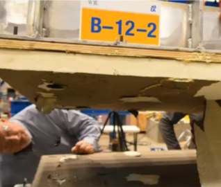
RICHARD KOZIOL
Okay. Thank you, Pat. Before we get into the test results, I just would like to mention that we developed a naming convention for the samples. We used the letter A, who designate polymer coated glass fiber face insulation, and the letter B to designate a cellulosic felt facer. In this image, you can see it's the best sample. There's A-18-2 that would mean A would be the polymer coated glass fiber facer, 18 inch ribbon sample number 2. Let's just kind of recap or summarize that again, we tested 18 full size 4 ft by 4 ft adherence specimens. The two facer types and there were 3 specimens each at 6, 12, and 18 inch ribbon spacings. The specimens were typically 4 to 6 days age at the time of testing in our lab and the conditions within our lab space were approximately 70 degrees Fahrenheit, and 30% relative humidity.
Here's a table showing the test results for polymer coated glass fiber facers. Again, you can see there's three of each or so. The 16 that driven spacings offers per square foot strengths varying from 624 to 719 pounds, or difference of 95 pounds per square foot for an average strength of 674 pounds per square foot. That's a coefficient of variation of 7.1%. For the 12 inch ribbons, we varied from 126 pounds to 555 pounds, which is a difference of 129 pounds per square foot. The average test strength for that for 12 and were 497 pounds per square foot and that equated to a coefficient of variation of 13.1%. For the 18 inch ribbon spacings, we ranged from 329 pounds to 351 pounds, or a difference of 22 pounds per square foot. Average test strength was 342 pounds per square foot, fairly tighter and type coefficient of variation of 3.4%. But all those coefficient of variations are reasonable, and we consider it to be good coefficient of variation.
For the cellulosic felt facers or be does a data samples again with the six inch ribbon spacings. We varied from 558 pounds to 643 pounds, or a difference of 85 pounds per square foot. The average test strength was 614 pounds per square foot with the coefficient of variation of 7.9%. For the 12 inch ribbon spacings, we varied from 354 pounds per square foot to 426 pounds per square foot or a difference of 72 pounds per square foot between the three samples and that's an average test strength of 379 pounds per square foot and coefficient of variation of 10.7%. For the 18 inch ribbons, we varied from 274 pounds per square foot to 347 pounds per square foot with an average of 307 pounds per square foot, or a coefficient of variation of 11.9%.
This slide here shows really in tabular form the test results and in a graph form. You could see on the graph on the right just to recap there, we have ribbon spacings that are showing along the horizontal access there for spacings from 4 to 20 inch is a part and then the vertical axis from a load of pounds per square foot from 200 to 800 with an incremental division of 75 pounds per horizontal line or pounds per square foot for horizontal line. You can see the dots there are the actual plotted numbers that we had for each of the test specimens and the lines we call the fit curve because they're fairly uniform and they're relatively parallel to one another. Our testing found that there's a very strong relationship between strength and ribbon spacing.
The measure direct control and strength would increase as the adhesive form ribbon spacing decreased for both facer types. For ribbon spacing, and uplift strengths represented felt curve for the nine data points. There were nine data points, right? Nine of each faced with fiber 18 samples 4, and the Apollo Macola glass fiber face the solution was stronger than the soil cellulosic felt faced insulation boards. It was 9% stronger at the six inch spacing ribbon spacing, 25% stronger to 12 inch ribbon spacing and 10% stronger at the 18 inch ribbon spacing.
Well, here's a video. All of them. After we touched at each sample of the failure, showing that we would take the samples out and we'd put them onto a table that we could document the conditions and fail conditions while photographically and visually, and showing the various types of failures that occurred. There's an example of a cellulosic fell faced board. Let me just back up and I guess, I'll play that again. Again, we're taking it apart after the load has been documented a failure to them separating it, and then we would take each specimen like this unfolded like a book and use that lift on the left side, as you can see, so you can get the nice aerial shot in what document the findings. There's a closeup of the cellulosic facer, and you can see the ribbon spacings here where it's peeled off in the testing. The primary failure plans that we found were the lamination and separation of the facer from the insulation and failure within the polyiso body of the board itself and shown here, circled in red would be the form separating them internally.
We did not ever have any failures in the low-rise foam adhesive itself. Only in the facing of the insulation and the foam body of the insulation. Typically, the failures on the foam body we're always at the higher loads. Here's an example in this photograph. This is a specimen, a polymer coated glass fiber facer, 12 inch ribbon spacing, simple number 2 and you could see the entire facer is a visible and wish we were seeing remnants of the polyiso insulation separating and pull the prime internally. In this particular sample, we had a failure load of 555 pounds per square foot. Here's another example. This is a specimen 862. Again, a polymer coated fiberglass face specimen. Look ribbon spacing and because we had a closer spacing, we had a higher load and this particular load failure was at 682 pounds per square foot. You could see how pulled apart and separated the foam core or foam body of the insulation occurred and again, no failures at all in the low-rise foam that was used to adhere the insulation together.
Here is a shot of cellulosic felt specimen with 12 inch ribbon spacing and you can see separation of the facer from the foam body on the insulation board. On the left-hand side of the test specimen, there were... I'm kind of... got my head down and then looking in there, lining up with my hand. You could see that the flattened low-rise foam and he's a ribbon remained in place, but the felt facers itself separated off of the adhesive. What we would term then to be like a cohesive failure plan all within the cellulosic felt the facer.
We perform testing on smaller sample specimens, a 12 by 12 samples to check the results against the 4 ft by 4 ft specimens. We also tested a low-rise foam adhesive itself. Then measure the strength of the adhesive. Here's a slide showing a sample of what we did with the 12 by 12 specimens. They were 12 inch by 12 inch specimens. They were very much like the four by four, just smaller, but they had a single ribbon placed in the center line of the sample and had the same peanut configuration through the plywood for use and being able to touch in a pencil machine. But we did this in a different test devices, will be seen in a slide or two here. Then we also tested the low-rise foam adhesive on what we termed the aluminum pucks, and here's a photograph of it.
The foam adhesive... to measure the strength of all my foam we used specially configured aluminum pucks and these are two inches in diameter pucks that have a smooth machine faced on one side and a threaded hole on the center of the other side. That we're there to receive a threaded rod for use in putting in direct tension testing. Then we also tested... while we tested two types of pucks. One, we tested eighth inch separated gaps based between the pucks and we did that because we noticed when we fabricated the samples of the four by four samples, that when we applied the weighted backers to the sample we would end up with about approximately an eighth inch thick adhesive flattened from the weight.
We thought that would be good so we devised that would create a gap space between the pucks, so that when we applied the adhesive, it would be representative of the actual 4 ft by 4 ft specimen. We also just tested the adhesive itself and just by placing the pucks and the weight on top, that would end up being a very thin layer of a use of typically less than a 16th of an inch and we tested that as well.
Here on the left, we have a view of the 12 inch square specimen and position being tested on what we call safe buck test machine and on the right of the two inch diameter pluck with low-rise foam adhesive, a gap that the eighth of an inch. As I mentioned, we made that gap space to represent what we observed as being common and typical for the flattened condition of the adhesive after the weighted backers were applied. Here's what we found in our testing for the companion 12 by 12 specialists. We tested 3 of each site, or the polymer coated specimens. We had a strength that average from 660 pounds to 700 pounds per square foot with an average of 673 psf and that was a fairly tight coefficient of variation, but for the cellulosic sample, samples B-1 through B-3, we had a high variability. We had a load varying from 435 pounds per square foot, all the way up to 660 pounds per square foot and that's a pretty high coefficient of variation and it's underscored.
I think one reason why it was a good idea to test the full 4 ft by 4 ft sized specimens. To the check ourselves, we wanted to just test... what if we made a full coverage specimen in other words, not a remnant, but we completely covered of the entire 12 by 12 area with low-rise from adhesive and we did that for one sample and the samples called FCA would be full coverage of the polymer coated of A specimen and that was 896 pounds for that one sample and full coverage B was the cellulosic 838 pounds per square foot. For the Companion Test-Puck, the companion tests for the pucks with the eighth inch, look at it we had some interesting results. We tested at 2 days, and then at 5 days aging. Because to the pucks and the way the test machine works on the Saitek, those test results were measured in pounds per square inch so for example TBS-1 and 2, right there 11.4 11.1 psi respectively. That equates to average pounds per square foot of 1,354 pounds per square foot with the coefficient variation of 33.9%, because we have an outlier there that was a 5.7% and then for the five-day specimens, you could see that the psi strength went up significantly by more than two times. It's a 3,365 pounds per square foot.
These are given again at PSI versus PSF because all of the measurements made in our testing of the four by four samples were impossible square foot so we converted over to have this be in the same units as the strength and pounds per square foot that we were just talking about in all the previous slide. The puck that was the less than 16th inch thick adhesive measure 295 psi and it shows that the average... I'm sorry, not the average, but the strength of 42,480 pounds per square foot. Let's discuss the findings and significance of these test results. The measured loads were relatively high and indicative of a good application because... if he's ribbons were fully mobilized and by that I mean, those really backers make a big difference and being able to get a full spread and contact of that low-rise foam adhesive to the facing skin of the insulation and when you do that, you will optimize the performance of the strength of the insulation buck but to keep in mind that these measures loads don't include any safety factors, although they were high which would need to be applied.
The polymer-coated facers was exhibited higher strength than the cellulosic facers for the testimonials are shown in the graph on the right so just to give an example, what would be like a typical uplift strength for, let's say an average building in the Midwest. Well, that answer to that question involves a lot of different variables that need to be considered and factored in, things like the height of the building, the building's geometry, the type of edge detail it has, whether it is a permanent wall or not, the use of the building, topography, risk factors, others, just to name a few of the variables. Let's say a small building under 60 feet tall in the Midwest, uplift service load might be anywhere between 15 to 50 pounds per square foot, and then perhaps 30 to 90 pounds per square foot of raider. We're building this taller than 60 feet.
The bond strength... failure of the specimen strength is primarily occurred at two plans or locations. The first type location was at the plane of the facer with the foam body and a failure at the plane was the lamination and separation of the insulation board facer from the former core. The second type of failure that occurred was that failures within the foam core itself, the low-rise heat of itself never failed either within the adhesive or at any interfaces with the facers and that was the case for all 18 specimens. Did he so strength of the polymer coated fiberglass facers to the foam core was much more consistent compared to the cellulosic face specimens tested and the strengths that we measured were significantly greater than typical uplift ratings for roofing systems. But again there were no safety factors applied to those loads that were measured. The strength testing of the 12 by 12 inch companion specimens didn't correlate well with the full-sized specimens. You remember that slide where we had the coefficient of variation of, I think 33 or 4%.
The testing of the full size four by four specimens where there to provide much more realistic and representative data than the smaller specimens. For the foam adhesive tested with the aluminum pucks, we had strengths greater than two and a half times. From age it shows that the increases by going from two days to five days of the strength increased by two and a half times a greater, but the testing was minimal when we tested just adhesive by itself... check this minimal thickness of adhesive by itself, but it produced really significantly greater strengths compared to the eighth inch thick tested specimens.
Again, this underscores the importance of waiting down the boards during an insulation to allow for lateral spread of the adhesive to get as wide of a contact area as possible so that you can get the optimal strength. Some of the limitations we had with the testing that we perform and want to point those out. All of the test information was derived from one manufacturer's product, for both the insulation and the adhesive, and the number of duplicative samples which was 18, presents some limitations in performing a statistical analysis to be able to interpret for useful roofing systems or assemblies, because we only tested one component of the typical roof system, right? The insulation bond to insulation. This data is not the same as values for like a full roofing system, which would include a cover board and the membrane, and other components like the vapor retarder that may be present in the assembly.
We'd like to continue doing some testing to include and recognize factors that can affect adhesive strength and that were not studied such as temperature and moisture ranges, the differences of temperature and moisture. Surface contamination and what influence or impact that would have on the testing. Obviously, it would bring it down and we'd like to know what would be tolerable, the insulation thickness was 2 inches. We don't know if there's any difference between one inch and three inch, for example and we like to be able to check that and see that consistency and amount of ballasting panels that mentioned that we use 26 pounds because that was the recommendation, I think, from the manufacturer that we used and it was subtracted from the weight of the plywood, et cetera. But what influence does that have on getting these results?
Obviously we know from the testing made that if we can mobilize that adhesive by making the maximum contact of the adhesive to the facer, we will achieve the maximum spread, but the revelation was that it's not really the adhesive that fails ever. It's the insulation itself, the facer delaminate or the foam core of bodies is the limiting factor for failure. We'd like to able to test and check moisture within the substrate as a possibility. In fact, they're two for example doc moisture. In summary we need to consider the test data and synthesize the information with design installation practices. Do you need to review written spacings and test of roof systems and also review the need and required its factors of safety for uplift performance. It would be good to evaluate and test multiple manufacturers insulation products on a use of products, because again, we only tested one manufacturer's product and adhesive so that concludes the presentation and at this time we'd like to open it up for questions.
LIZ PIMPER
Thank you Rich.
RICHARD KOZIOL
Probably take over to Liz.
LIZ PIMPER
Yeah. Thank you Rich and thank you Pat for the presentation. As a reminder, you can type your questions into the Q&A box and hit submit, and we'll try and get to all the questions during the call, but if we aren't able to get your questions today, then Rich and Pat will follow up with you afterwards. Okay. Let's take our first question. Why did you test four-foot specimens, doesn't the industry use two-feet in the field?
RICHARD KOZIOL
I'll take that one, Liz. First of all, the MRCA asked if we could test full-size specimens, that was a question in their problem statement and we thought that was a good idea. We didn't want to deviate that and we weren't... we know that there are standards for two-foot that the side, for example, the ANSI and FM standards. We were aware of those and but we felt that with the four-foot specimens, we could negate any influence that would have from for example, a tripod is typically used. There's some influence of self reacting forces in that test frame and we didn't have any of that. Plus we tested 4 by 4, 16 square feet versus 4 square feet so we tested so much more area. We think that's more indicative of more areas. We were able to see more of the ribbon space used, right? It was more than just one ribbon and we think that made a difference for us in our testing. I hope that's…
LIZ PIMPER
Okay. For the next question starts. I'm sorry if you already noted this, but did you test the same thicknesses of insulation or varying thicknesses?
PAT SHAUGHNESSY
I'll take that. Because of that... just two inch it's a very common thickness of ventilation that's used in the industry so get two inch was the only thickness that was tested. It would be interesting to see what if we were to use thinner thickness insulation or thicker and see what those results are.
LIZ PIMPER
Okay. Our next question, how does the PSS of resistance relate to wind uplift design factors?
RICHARD KOZIOL
I'll take that. Well again, the building codes spectra... each building is different it's got its own unique geographic location and so there's a formula that is used. All those factors are determined, but including wind, speeds are provided in the building code. There is an equation that you have to go through to calculate these loads it's pretty involved. But the building code prescribes what and how did to determine that and what we find whenever we do a roofing project, if we're either designing one or doing replacement design, we always check the wind uplift load required for that site and use that in our specifications.
LIZ PIMPER
Okay. Our next question, I'm in Chicago, we're commonly installing in 40 to 45 degrees temperatures, which affects the foam adhesive. Do you plan on replicating the test on the lower end of the recommended roofing installation temperature range?
RICHARD KOZIOL
I'll take that. That's a great question and that is something that we are discussing right now with MRCA. We think that's an important thing to check for and test. Obviously, didn't test for it in this study here, but we think it's a good subject to test and to look into and we plan to do that in the future.
LIZ PIMPER
Okay. Our next question. My takeaway from this is that ribbon insulation in the field should be maintained at the 3, 4 inch size to be spread as thin as possible. I would assume that if we see glob being installed, we should consider that wrong.
PAT SHAUGHNESSY
I'll take that. I think maintaining the three quarter inch to one inch thickness that the ribbon thickness at the manufacturers recommend is good. I think what's important is to make sure that you're getting that weight on the insulation and allowing that adhesive to spread to get that maximum bond and features for the insulation.
LIZ PIMPER
Okay. Next question. What was the criteria for failure? Was it the separation of the insulation panels? Sorry. Was the separation of the insulation panels a certain distance, or was it complete failure?
RICHARD KOZIOL
I'll take that. Well, we weren't really looking for criteria for failure to say we test it to failure and made measurements and observations of where the failure plane was. What was the second part of the question?
LIZ PIMPER
I believe the question was it considered failure if the insulation panels separated by a certain distance, or were you looking for a total failure?
RICHARD KOZIOL
We've measured, well, failure was defined as when the load was no longer sustainable. In other words when we... let's say, for example, we tested to a 600 pounds per square foot and then we could not apply any more load. We could visually see a separation that occurred and then we had a quick drop-off in the measure load, we couldn't apply any more force essentially. That was our maximum load at failure. Again, by having that center yoke, we were constantly measuring deflections to see that we were getting a nice uniform pool. We did for all 18 pretty uniformly made because we measured those transducer loads which are not given in this presentation, but which we did record and provided in the report to the MRCA. That was important during the testing for us to be able to check and monitor that.
But the center yoke was really the key in being able to get a nice uniform pool that didn't really peel a PRI from one end or the other so the failures that occurred, occurred as a result of the uniform pool. In some locations we had the appealing of the facer versus a foam core body that occurred just naturally because we did provide a consistently uniform direct tension pull that did not have any preying action.
LIZ PIMPER
Okay. We've probably got time for one more question. Would you recommend different adhesive spacing for different facers or insulation densities, depending on their failure rates flash points?
PAT SHAUGHNESSY
I don't think we're recommending changing the spacing that's required by the manufacturers, but I think it's interesting the insulation densities could be another avenue for testing in the future.
RICHARD KOZIOL
Right.
LIZ PIMPER
Rich would you like to add something.
RICHARD KOZIOL
No, I mean, I agree. I think that the insulation densities is also important, but it does underscore and show that... again, the limiting factor here is the insulation is really the weak link in the system. It's not the low-rise foam adhesive, it's the insulation and so by spacing the variable ribbon spacing apart, we know for example from and this we don't want to deviate from what the manufacturer say, but that four inch ribbon spacing you're almost doing full coverage. I would say because you get a spread of three inches or three and a half inches by using weighted backers. That's about what the flattened surface of a typical beat of. I mean, of course there's variability in that number that I just said, but you get a round, a three inch wide spread by putting these weighted backers down and if you did that four inch ribbon spacings, you're almost getting full coverage of adhesive. Maybe you want that in some cases and maybe it's unnecessary in others.
LIZ PIMPER
Okay. That is all the time that we have for questions today. Like I said, if we didn't get to your questions, Rich or Pat we'll follow up with you. But thank you so much for joining us today and thank you Pat and Rich for the presentation. We hope it's been educational. If you have any questions about the presentation today, please don't hesitate to reach out to Pat or to Rich, the contact information is on the screen and if you have any questions about WJE webinars, please contact me at lpimper@wje.com and so again, thank you so much for your time and we hope you have a great rest of the day.
RELATED INFORMATION
-
 WJE's Janney Technical Center (JTC) provides advanced testing and forensic capabilities to... MORE >Labs | Janney Technical Center
 -
 We offer in-house expertise for a full range of investigation, analysis, and design services... MORE >Services | Architectural Finishes and Materials
 -
 Our materials scientists provide comprehensive consulting services for the evaluation and... MORE >Services | Materials Evaluation and Testing
 -
 Overview of research and testing program and summary of results MORE >Webinars | Findings of Low Rise Foam Adhesive Testing Program